HyperXite 8
Hyperxite.com - Innovating the future of travel, Lead Propulsion Engineer
![]()
Throughout the 2022-2023 academic school year, I worked on HyperXite 8’s Linear Induction Motors as the lead Propulsion Engineer. to compete at the European Hyperloop Week International Design Competition.
Design Overview
This project is still in progress, and we are hoping to create our first (of four) Linear Induction Motors in the coming weeks.
Some of my favorite analytical work is displayed below:
Rotor Analysis
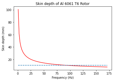
As the frequency increases, the stator field will be unable to penetrate the rotor and the two stators will be decoupled and operate independently. Under this condition, the field sticks to the surface of the rotor instead of penetrating through the entire rotor thickness and field energy is lost as it is absorbed by the I-Beam and dissipated as heat.
If the frequency of the produced field is low enough, defined by the skin depth of the rotor, the stator field will penetrate through the I-beam and reach the matching stator on the other side of the rotor. When the magnetic field line paths close on themselves, the pair of stators is coupled together.
Notably, at a frequency of 92.605 Hz, we observe that the penetration depth becomes lower than the thickness of the I-beam, and therefore any further increases in frequency result in the decoupling of the motor. However as we are operating at low speeds, we can safely assume we will not have a decoupled LIM pair.
\[\delta=\sqrt{\frac{2\rho}{\omega\mu}}\]
Derivation of current driven Force Formula
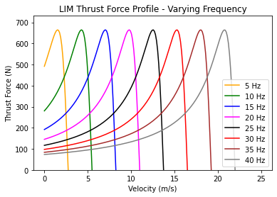
This derivation of force for our dual stator linear induction motor design parameterizes force in terms of the frequency of the induced stator field in the rotor. By modulating the inputted three phase AC power’s frequency we are able to utilize the difference in sync and mechanical speeds to maximize the thrust of the motor for any given velocity.
\[F_{thrust} = \frac{18Θ^2Dd_rσL(v_s-v_r)}{(\frac{πg}{μ})^2+(v_s-v_r)^2(σd_rτ_p)^2}\]From integration of 2.82 from Linear Induction Motor (LIM) for Hyperloop Pod Prototypes
For \(v_s = \frac{Lω}{2π}\), \(τ_p = \frac{L}{2p}\), \(p = 1\), and for \(4Θ = IN\):
Gives us our final thrust formula:
\[F_{thrust} = \frac{18Dd_rσLN^2I^2(\frac{Lω}{2π}-v_r)}{(\frac{πg}{μ})^2+(\frac{Lω}{2π}-v_r)^2(σd_r\frac{L}{2})^2}\]# Variables
N = 164 # Turn number, number
I = 54 # Current, amps
g = 0.04248 # Air gap, m
mu = 1.25663753E-6 # constant, permiability of air, H/m
D = 0.1 # Stator width, m
dr = 0.01048 # Rotor width, m
rho = 4E-8 # rotor_resistivity, ohm/m
sigma = 3.03E7 # rotor conductivity
L = 0.55 # Stator length, m
Finally, performing a parametric sweep across our formula allows us to always operate the linear induction motor at its peak performance, as shown below.