HyperXite VII
Hyperxite.com - Innovating the future of travel, Braking Engineer
![]()
Throughout the 2021-2022 academic school year, I worked on HyperXite VII’s braking subsystem as an Braking Engineer to compete at the European Hyperloop Week International Design Competition.
Design Overview
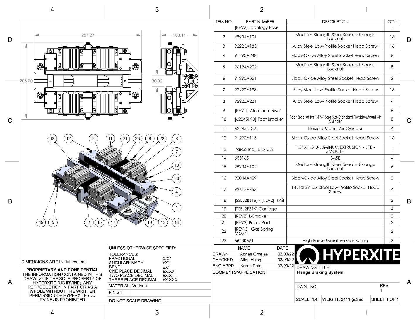
The HyperXite VII braking system is a single acting pneumatically actuated fail safe braking system built from the ground up to be robust and durable. The fail safe behavior of the braking system is derived from four 173 lbf gas springs being restrained by twin pneumatic actuator assemblies. The system is designed such that in the event of an unexpected loading condition the gas springs are to over come pneumatic resisting force, vent the system, and apply the full braking force onto the track.
Design Conceptualization
This year we worked on iterating on the previous year’s design. During HyperXite VI, the braking system was a double acting pneumatically actuated system that operated at 120 psi, however there were fundamental issues with the design which resulted in the eventual failure of the braking system during a pod test. In addition to this, once the braking system failed, there was no additional fail safe to aid in the event of braking failure.
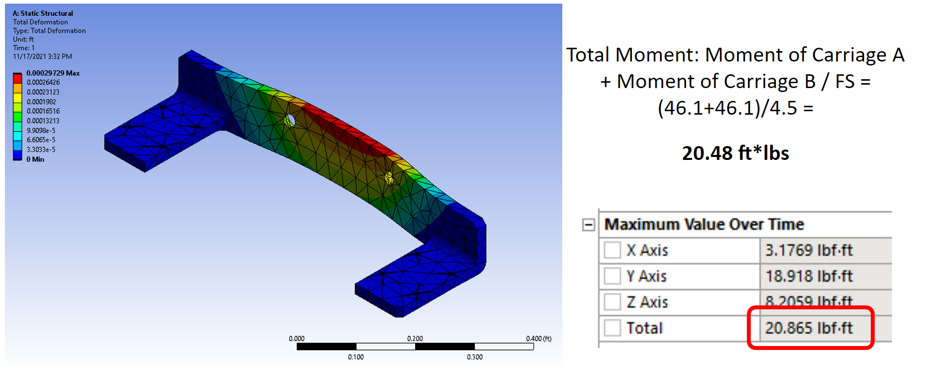
Early on in the design conceptualization phase I noted that the Factor of Safety of 2 was not met with the previous year’s braking system due to an error in the initial hand calculations that were created. After identifying the error I was able to successfully validate my hand calculations that used 2D simplifications in a full 3D Finite Element Analysis in ANSYS Mechanical resulting in a 1.8% error.
Continuing, we as a team wanted to further improve the new design in order to ensure the safe operation of the breaks. Moving forward, I proposed to reuse the existing hardware we had on in inventory in order to cut down on upfront costs and simplify the engineering design constraints. Even with many of the hardware variables reduced, the challenge of meeting all required design variables was substantial. As a result, I iterated through 27 different variations on the braking system, below are some notable designs that I modeled in SolidWorks and validated in ANSYS Mechanical FEA. (My personal favorites being the following two designs)

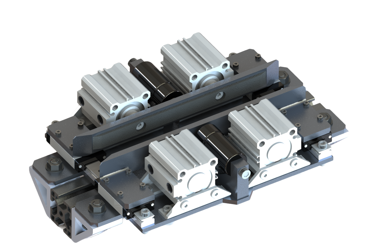
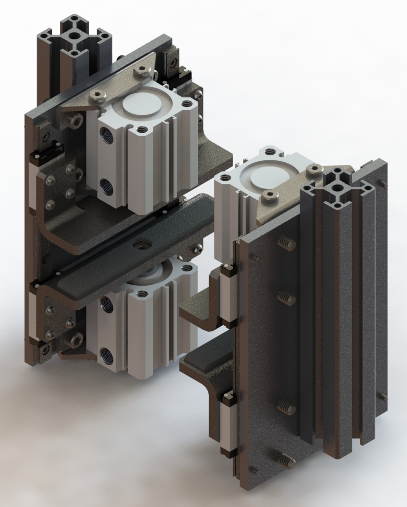
Linear Rod Braking Design Concept
Double Actuator Braking Design Concept
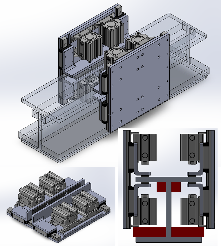
Eventually, we decided to pursue the double actuator braking design concept further. While the initial concept was not a fail safe design and relied on pneumatic pressure at all times during operation, we aimed to create a fully redundant system that was not tied to any subsystem on the pod. In order to allow our braking system to enter a safe state upon pod failure, we needed to convert our double acting pneumatic cylinders to Fail Open behavior. I addressed this by integrating a miniature gas spring in between our two pneumatic actuators. I determined the best position by heavily revising the braking system to optimize size, weight, and the distribution of moments on our linear rails. Ultimately, the final braking system design was completed by the end of February 2022, and more information can be found in the included design binder.
Manufacturing and Validation
Manufacturing of the Braking System began in the Winter Quarter of 2022 (January 2022), and included some of my absolute favorite engineering memories from my time at UCI. All throughout the manufacturing process I was met with memorable experiences and getting comfortable in my machinist abilities.
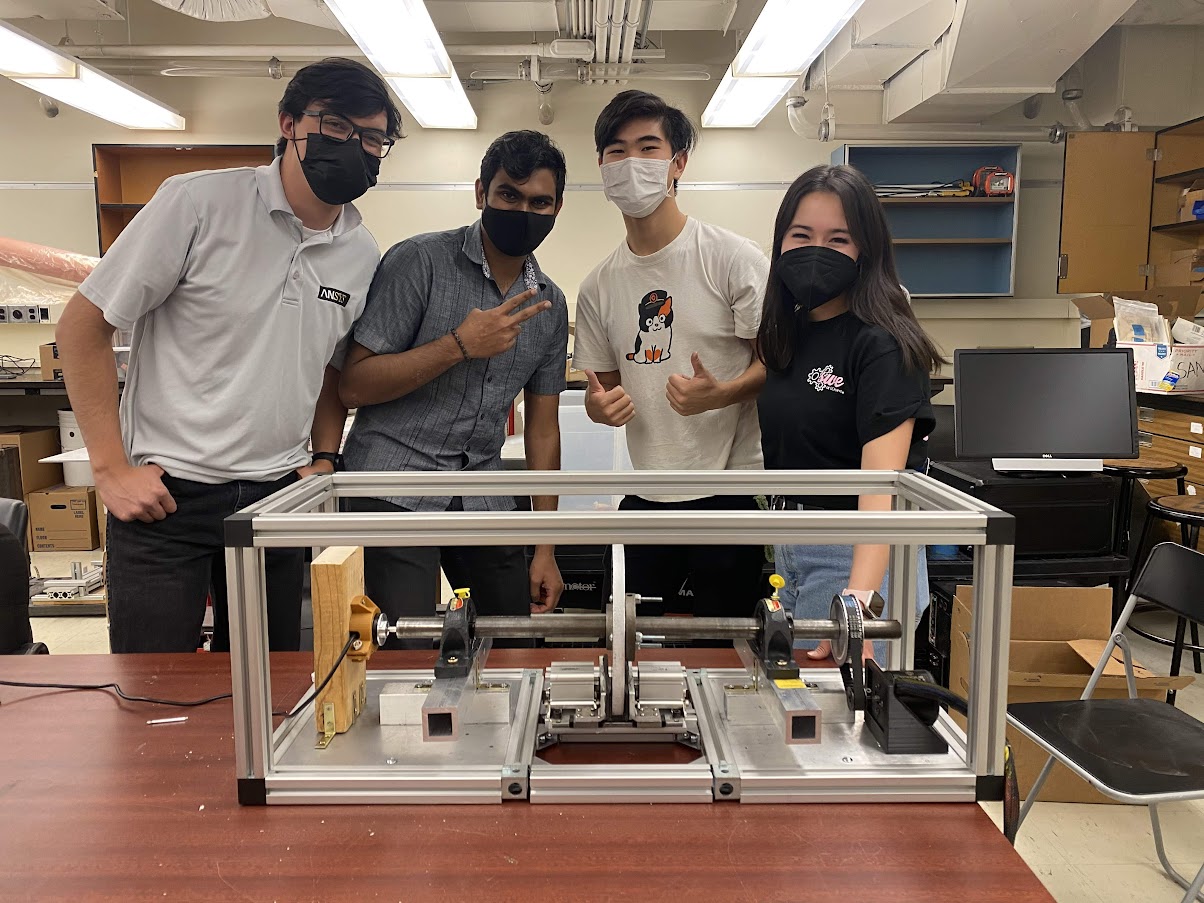
One of the key moments of the the assembly of the brakes was not the brakes themselves, but instead the Braking Test Rig. The Braking Test Rig is an aluminum cage containing a sizable flywheel. In order to validate our braking system without accelerating the brakes linearly we instead decided to accelerate a flywheel through the brake pads and brake tangentially to create a more controllable testing procedure. As I was intimately familiar with the electrical systems of the HyperXite VI Pod from the previous year, I took it upon myself to integrate the Braking Test Rig electrically. By doing this I integrated the previous year’s motor controller, motors, and wrote a minimal GUI that allowed us to collected testing data easier. In addition to this, I installed several different safety mechanisms to ensure the safety of the team; among them Software and Hardware Emergency Stops, Electrical Braking, and safety checks. Eventually, the braking test rig became a great source of pride as we pushed the flywheel to speeds exceeding 1000 rpm, and ultimately validated the performance of our braking system. More information can be found in the design binder in the following section.
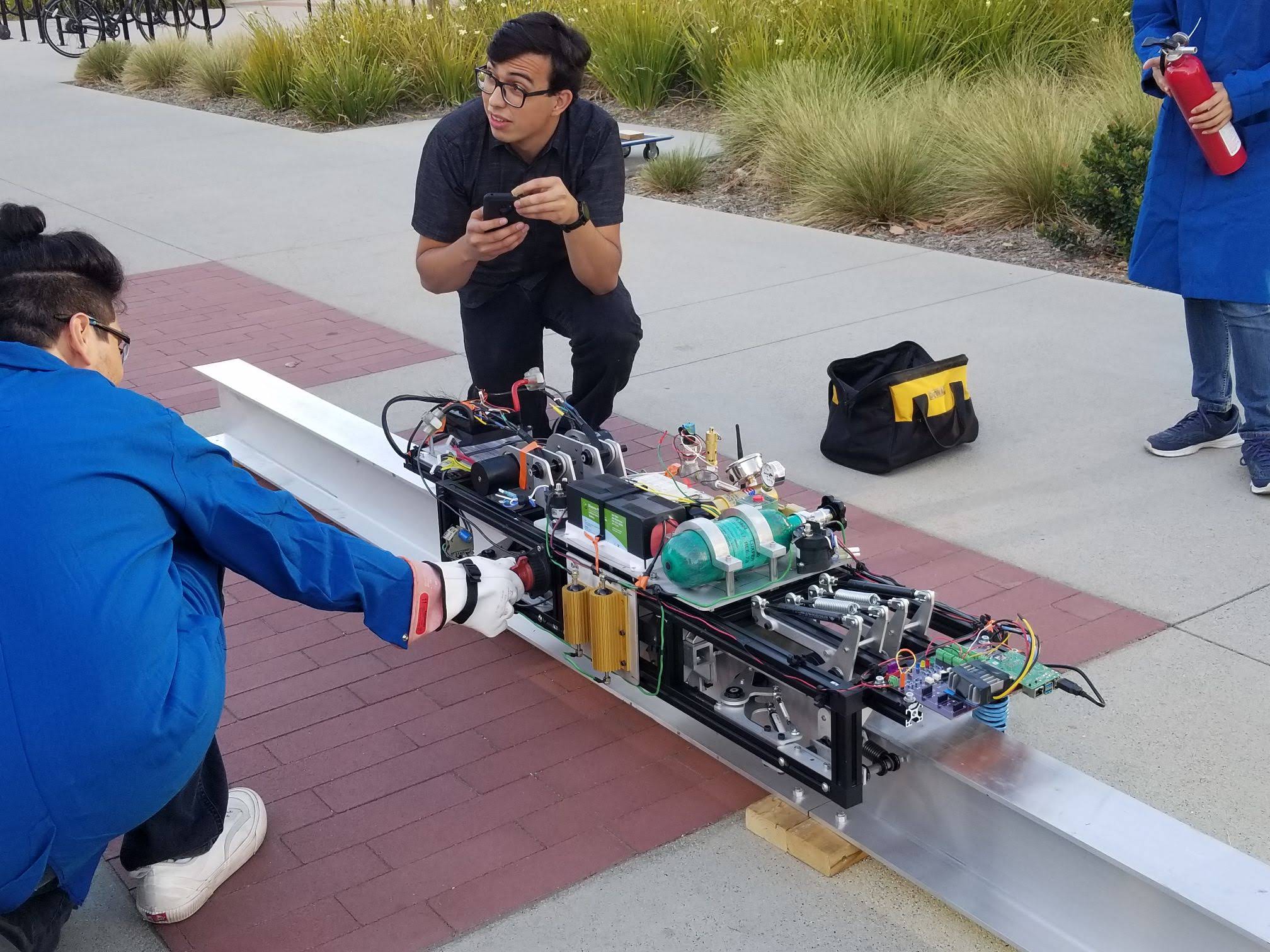
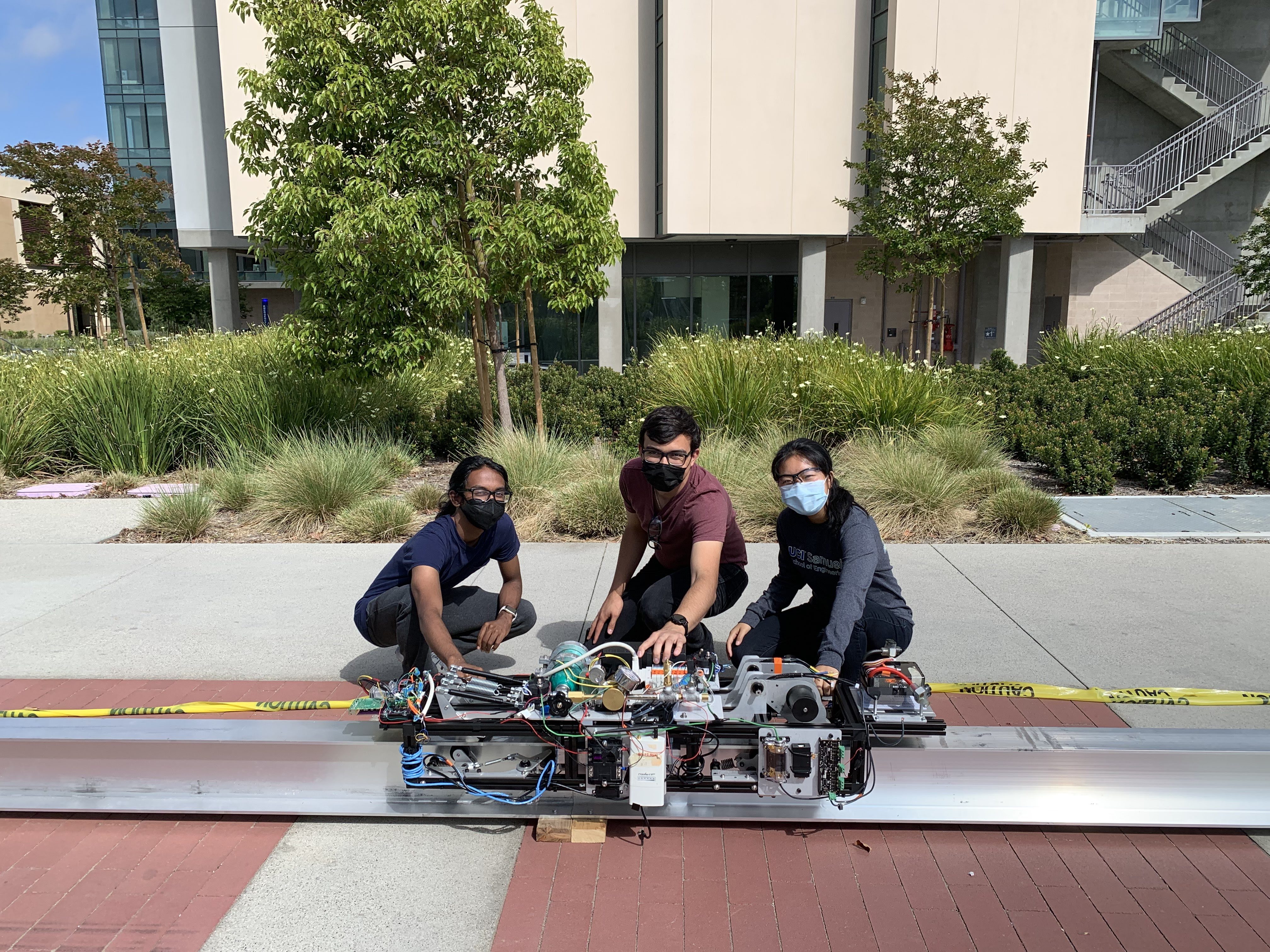
Finally in early June, we were able to complete full mechanical integration of the HyperXite VII Pod and begin full testing. Unfortunately due to circumstances that were out of our control, we were unable to completely run the pod and instead relied on a minimal control system that I controlled from a terminal on my phone. Through this we were able to stress test the various components of our pod under varying loading conditions. While we did not have the full power of the twin motors avaiable to us, we were able to successfully brake and validate the performance of the brakes in full scale testing.
Engineering Documents
Here are a list of important engineering documents that I created throughout the course of the project.